
Scope: NEV motors, industrial motors, servo motors and micro motors across all categories
1. Electric Motor Industry Overview
1.1 Electric Motor Industry Trends
As the core component converting electrical energy into mechanical energy, electric motors continue to see growing demand in industrial automation, new energy vehicles and smart homes. The global motor market exceeded USD 180 billion in 2025, with NEV traction motors the fastest-growing segment at a CAGR above 20%. As motor technology advances toward higher power density, higher efficiency, higher speed and lighter weight, heat flux density keeps rising, imposing more demanding requirements on thermal management, insulation protection and vibration damping. The adoption of oil-cooled motors, hairpin windings and carbon-fibre rotors also creates new application challenges for electronic silicone materials.
1.2 The Core Value of Electronic Silicones in Electric Motors
Value Dimension
Application
Benefit
Thermal management
Stator winding potting, magnet cooling
Reduces temperature rise by 15–30℃ and increases power density
Insulation protection
Stator end-turn insulation, slot opening protection
Prevents turn-to-turn short circuits and withstands high-voltage surges
Structural fixation
Magnet bonding, end-turn winding fixation
Withstands centrifugal loads above 20,000G and resists vibration
Sealing and protection
Housing sealing, terminal box sealing
IP68 dust and water protection, resistant to oil and coolant
Lubrication and friction reduction
Bearing grease
Reduces friction losses and extends bearing life
Vibration and noise reduction
Elastomeric potting compound damping
Reduces electromagnetic noise by 2–5 dB(A)
1.3 Motor Types and Corresponding Silicone Requirements
NEV traction motors: Stator (hairpin end-turn potting / trickle impregnation / insulation coating) → magnets (thermally conductive bonding) → oil-cooling port sealing. Industrial servo motors: Stator (potting / slot wedge fixation) → encoder (protection) → brake (sealing). Micro and stepper motors: Magnet bonding → bearing lubrication → end cap sealing. High-voltage motors: Stator insulation potting → slot corona protection → lead wire sealing.
2. Product Portfolio Overview
2.1 Core Product Series
Product Series
Product Name
Typical Model
Key Features
Thermally Conductive Potting Compound
Motor-specific potting compound
MT-2803/2804/2806/2808
Thermal conductivity 0.8–2.0 W/m·K, low viscosity, reworkable
Thermal Grease
High thermal conductivity grease
MT-3203/3205
Thermal conductivity 1.0–4.6 W/m·K, low oil bleed, long service life
Magnet Adhesive
High-strength magnet bonding adhesive
Bond strength >8MPa, withstands 200℃
Bearing grease
High-Speed Bearing Grease
Low starting torque, wide temperature range -60℃ to 260℃
Insulating Conformal Coating
Winding end-turn conformal coating
MT-2806
Dielectric strength >20kV/mm, full environmental protection
Housing Sealant
Oil-resistant silicone sealant
MT-6655
Resistant to ATF and coolant, FIPG formed-in-place
Insulating Impregnation Resin
Trickle-impregnation insulating resin
Low-viscosity penetration, fast cure, Class H insulation
2.2 Technical Advantages
Motor potting compound: low viscosity (≤3000cP) penetrates deep into stator slots and completely fills micro-gaps
Magnet adhesive: room-temperature or fast heat cure, oil and heat resistant, shear strength >8MPa
High-speed bearing grease: base oil uses ultra-high viscosity index silicone oil, evaporation loss <1% (180℃/24h)
Insulating impregnation resin: compatible with VPI (vacuum pressure impregnation), thermal class H (180℃) and above
All products comply with RoHS, REACH and UL certification; UL Yellow Card available
3. Motor Stator Solutions
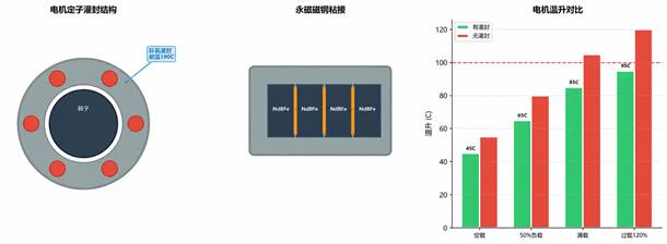
Figure 3-1 Motor stator potting and magnet bonding solution
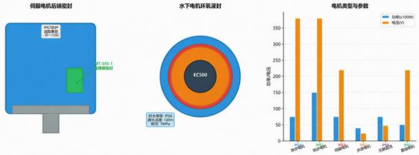
Figure 3-2 Servo motor sealing and selection guide
The stator is the focal point of motor thermal management. Copper losses in the stator winding are the dominant heat source, accounting for roughly 60–70% of total motor heat generation. End-turn heat dissipation, in-slot heat transfer and insulation protection are the key application areas for electronic silicones.
3.1 Stator End-Turn Potting Solution
Application area: stator end turns of hairpin and round-wire motors (exposed winding ends). Recommended product: MT-2804 motor-specific thermally conductive potting compound
Parameter
MT-2804
Industry Requirement
Assessment
Thermal conductivity
0.8~1.2 W/m·K
≥0.6
Excellent ✓
Mixed viscosity
2500 cP
≤5000
Good penetration ✓
Cured hardness
Shore D 45
Shore D 30~60
Well balanced ✓
Dielectric strength
22 kV/mm
≥15
Outstanding ✓
Thermal class
Class H (180℃)
Class H (180℃)
Compliant ✓
Cure shrinkage
<0.15%
<0.3%
Low shrinkage ✓
Working time (25℃)
45min
≥30min
Ample ✓
Recommended potting processes. Option A — full mould potting:
- Pre-heat the stator to 80℃ to remove moisture
- Install the potting mould and seal the end-turn area
- Vacuum-mix parts A and B → degas → pour under low pressure
- Step cure: 80℃ × 1h → 120℃ × 2h → cool naturally. Option B — trickle potting for end-turn fixation:
- Position the stator at a 45° tilt
- Feed the compound from the highest point of the end turns and let capillary action carry it in
- Rotate the stator to cover all end turns evenly
- Heat cure at 120℃ × 1h
3.2 In-Slot Insulation Impregnation Solution
Parameter
Process compatibility
Viscosity (25℃)
800 cP
Suitable for vacuum pressure impregnation (VPI)
Gel time (130℃)
5~8 min
Suited to fast production line cycles
Bond strength (to copper)
12 MPa
Firmly secures conductors
Dielectric strength
25 kV/mm
Higher than insulation paper
Thermal class
Class H (180℃)
Meets NEV motor requirements
Tg (glass transition temperature)
170℃
Maintains rigidity at high temperature
Recommended VPI process:
- Pre-heat the stator to 100–120℃ and hold for 2h to remove moisture
- Place in the VPI vessel, evacuate to ≤100Pa and hold for 30 min
- Introduce ID300 resin and vacuum-impregnate for 15–20 min
- Return to atmospheric pressure, then pressurise to 0.3–0.5MPa and hold for 10 min
- Allow 30 min for excess resin to drain
- Heat cure: 130℃ × 1h → 160℃ × 2h
3.3 Hairpin Weld Joint Protection Solution
Application area: hairpin winding weld ends (King Coil Crown zone). Recommended product: MT-2806 insulating conformal coating. Technical requirements:
- Apply immediately after welding to ensure full wetting of the terminals before cure
- Insulate the weld joints against high voltage and partial discharge
- Protect weld joints from coolant and oil mist attack
- No cracking under -40℃ to 180℃ thermal cycling
- Selective spraying or dip coating is recommended, with a coating thickness of 100–300μm
4. Motor Rotor Solutions
4.1 Magnet Bonding Solution
Parameter
Test Condition
Shear strength (to ferrite)
10 MPa
25℃
Shear strength (to NdFeB)
8 MPa
25℃
High-temperature shear strength
4.5 MPa
150℃
Operating temperature
-55℃~200℃
Continuous operation
Cure method
80℃ × 30 min or 25℃ × 24h
Can be accelerated by heat
CTE (coefficient of thermal expansion)
80 ppm/℃
Well matched to metals
Oil resistance
Retains >75% strength after 1000h in ATF oil at 150℃
Long-term immersion
Key bonding process points:
- Degrease the core slot walls and magnet surfaces (plasma treatment recommended)
- Complete assembly within 15 min of adhesive application
- Apply 0.1–0.3MPa clamping pressure after inserting the magnet
- Heat cure: 80℃ × 30 min (recommended for production lines)
- Sample-test magnet pull-out force after cure; standard ≥3kN
- Re-confirm that magnets have not shifted after high-speed rotor balancing
4.2 Magnet Thermal Management Solution
Application areas: the thermal interface between magnets and rotor core, and rotor end cooling. Recommended products: MT-3203 thermal grease / MT-2804 thermally conductive potting compound. Demagnetisation risk rises sharply at high temperature, so effective heat dissipation is essential to keep magnet temperature down. Option 1 (magnet slot filling): MT-2803 potting compound fills the gap between magnet and core, thermal conductivity 1.0 W/m·K. Option 2 (magnet back coating): MT-3203 thermal grease applied to the magnet backside at 100–150μm. Option 3 (rotor end coating): MT-2806 conformal coating over the rotor ends for supplementary heat dissipation. Result: magnet temperature reduced by 15–25℃ and demagnetisation resistance improved by more than 30%.
4.3 Rotor Dynamic Balancing Compensation Solution
5. Motor Controller Solutions
5.1 IGBT / SiC Module Thermal Management Solution
Application area: interface between the IGBT / SiC power module and heat sink in the motor controller
Comparison Item
MT-3204 thermal grease
Thermal conductivity
3.7 W/m·K
3.0 W/m·K
Thermal resistance (@50psi)
0.05 ℃·cm²/W
0.12 ℃·cm²/W
Applicable gap
50~150μm
0.5~3mm
Automation efficiency
Stencil / screen printing — fast
Pad placement — slow
Ease of rework
Requires cleaning and re-application
Easily peeled and re-applied
Recommended use
High-volume automated production lines
Multiple chips with height variation / low volume
5.2 Controller PCB Protection Solution
Application areas: motor controller control board and driver board. Recommended product: MT-2806 insulating conformal coating. Automotive-grade requirements:
- Thermal shock resistance: -40℃ ↔ 125℃, 500 cycles
- Vibration resistance: 20G random vibration for 100h
- Corrosion resistance: 100h salt spray with no migration
- Coating thickness: 40–100μm
5.3 DC-Link Capacitor Potting Solution
Application area: internal filling of DC-link capacitors. Recommended product: MT-2804 (high dielectric strength grade). Key requirements:
- High dielectric strength: ≥30kV/mm
- Low dielectric loss: Df ≤0.001 @1kHz
- Low CTE matching: consistent with the aluminium can and film
- Long life: no performance degradation after 2000h at 85℃/85%RH
6. Bearing and Lubrication Solutions
6.1 Bearing Lubrication Applications
Application areas: front and rear motor bearings, deep-groove ball bearings, angular contact ball bearings
Motor Type
Bearing Specification
Recommended Grease
Life Target
NEV traction motor
6305~6315
≥150,000 km or 8 years
Industrial servo motor
6200~6208
20,000h continuous operation
In-wheel motor
Custom formulation
≥100,000 km
EPS steering motor
Miniature bearing
Maintenance-free for life
Oil-cooled motor
Special sealed bearing
≥8000h
6.2 High-Speed Bearing Grease — Technical Data
Parameter
Base oil
Modified silicone oil
Perfluoropolyether (PFPE)
Thickener
Polytetrafluoroethylene (PTFE)
Polytetrafluoroethylene (PTFE)
Operating temperature
-60℃~220℃
-40℃~260℃
DN value (n × dm)
≤1.0×10⁶
≤1.5×10⁶
Starting torque (25℃)
≤30 g·cm
≤40 g·cm
Evaporation loss (180℃/24h)
<1.0%
<0.5%
Water resistance
Outstanding
Outstanding
Typical application
Standard motors and servo motors
NEV traction motors and oil-cooled motors
Key grease filling process points:
- Degrease, clean and dry the bearing
- Fill volume: 25–35% of internal bearing space (high speed) or 35–50% (medium to low speed)
- Run the bearing for 2–3 min after filling to distribute the grease
- Re-check grease distribution after fitting the dust cover or seal ring
- Never mix greases of different brands or base oils
7. Motor Housing and Sealing Solutions
7.1 Housing Sealing Solution
Application areas: front and rear end cap-to-housing joints, cable outlets, oil and water ports
Sealing Area
Recommended Product
Protection Rating
Key Features
End cap joint face
MT-6655 silicone sealant
IP68
FIPG formed-in-place, resistant to oil and coolant
Cable outlet
MT-6655
IP68
Compatible with cable jackets, non-corrosive
Oil-cooling port
MT-6655 (oil-resistant grade)
IP69K
No leakage after 1000h in ATF oil at 150℃
Water-cooling connector
MT-6655
IP69K
Coolant resistant and hydrolysis resistant
Terminal box sealing
MT-6655
IP67
Gasket-free, applied directly
7.2 Terminal Box Potting Solution
Application area: three-phase lead terminals inside the motor terminal box. Recommended product: MT-2804 (oil-resistant grade). Key requirements:
- Insulation resistance ≥500MΩ (DC 1000V)
- Withstand voltage ≥3kV for 1 min with no flashover
- No degradation of electrical properties after oil immersion
- UL94 V-0 flame retardancy
8. Selection Guide and Technical Data Comparison
8.1 Quick Selection Matrix
Application
Primary Requirement
Recommended Product
Alternative Product
Stator end-turn potting
Thermal conductivity + fixation + insulation
MT-2804
Stator VPI impregnation
Penetration + insulation + cure
—
Hairpin weld joint protection
Insulation + temperature resistance
MT-2806
MT-2804
Magnet bonding
High strength + temperature resistance
—
Magnet heat dissipation
Thermal conductivity + insulation
MT-3203
MT-2804
Rotor balancing compensation
Precision + high adhesion
—
IGBT / SiC cooling
High thermal conductivity + low thermal resistance
MT-3204
Controller PCB protection
Environmental protection + insulation
MT-2806
—
DC-link capacitor potting
High insulation + low loss
MT-2804 (high dielectric grade)
—
High-speed bearing lubrication
Low evaporation + temperature resistance + long life
Housing sealing
Oil resistance + IP68
MT-6655
—
Terminal box potting
Insulation + waterproofing
MT-2804
—
8.2 Product Selection Flowchart
Motor silicone applications ─┬─ Stator ─┬─ End-turn potting → MT-2804 │ ├─ VPI impregnation → ID300 │ └─ Weld joint protection → MT-2806 │ ├─ Rotor ─┬─ Magnet bonding → MA600 │ ├─ Magnet cooling → MT-3203/MT-2804 │ └─ Balancing compensation → MA600 (weighted) │ ├─ Controller ─┬─ IGBT cooling → MT-3204/TSP │ ├─ PCB coating → MT-2806 │ └─ Capacitor potting → MT-2804 (high dielectric) │ ├─ Bearing ── Grease → LG100/LG200 │ └─ Housing ─┬─ Sealing → MT-555-1 └─ Terminal box → MT-2804
9. Competitive Advantages
9.1 Technical Advantages
Motor-specific formulation platform: dedicated formulations for different motor types (hairpin / round wire, high / low voltage, oil / water cooled)
Low-viscosity penetration technology: MT-2804 potting compound has a viscosity as low as 2500cP and penetrates deep into micro-gaps within the slots
In-house magnet adhesive: replaces imported brands at 30–50% lower cost with performance benchmarked against world-leading products
High-speed bearing grease: PFPE-based perfluoropolyether grease delivering the longest life under extreme operating conditions
All products validated in our own laboratory, with complete reliability test reports available
9.2 Quality Advantages
Quality Metric
Industry Standard
Maxtor Control Level
Batch stability Cpk
≥1.33
≥1.67
Viscosity tolerance
±20%
±10%
Cured hardness tolerance
±10 Shore
±5 Shore
Thermal conductivity tolerance
±0.2 W/m·K
±0.15 W/m·K
Shear strength tolerance
±15%
±8%
Batch traceability
Batch traceable
Samples retained for 5 years with complete process records
9.3 Service Advantages
- Free samples: trial samples matched to the customer's process shipped within 24 hours
- On-site production support: engineers deployed on site for the first mass production run
- Process optimisation: assistance in optimising dispensing and potting parameters to raise yield
- Joint development: custom formulation development for new motor designs
- VAVE support: ongoing cost-reduction proposals to help customers optimise material cost
10. Case Studies
Case 1: Stator potting for an NEV traction motor
Customer background:
A top-3 Chinese NEV e-drive supplier, 200kW hairpin motor platform
Requirement:
Stator end-turn potting with thermal conductivity ≥0.8 W/m·K, thermal class H, and a post-potting temperature reduction of at least 15℃
Solution:
Customised MT-2804 formulation with thixotropy tuned for vertical potting
Results:
- Stator end-turn temperature reduced by 18℃
- Potting cycle time cut from 5 min to 3 min
- Passed million-kilometre reliability validation
- Annual consumption exceeds 200 tonnes
Case 2: Bearing lubrication upgrade for high-speed servo motors
Customer background:
The China plant of a Japanese servo motor brand, 15,000 rpm high-speed servo motors
Requirement:
Bearing grease life ≥20,000h, low noise, suitable for high-speed operation
Solution:
Results:
- Bearing life increased from 12,000h to 25,000h
- Motor noise reduced by 3 dB(A)
- Cost reduced by 25%
- Rolled out across the customer's global plants
Case 3: Magnet bonding process optimisation
Customer background:
An NEV motor manufacturer facing a cycle-time bottleneck on its IPM rotor line
Requirement:
Magnet adhesive cure time had to be cut from 4h to under 30 min while maintaining shear strength ≥8MPa
Solution:
Results:
- Line cycle time reduced from 4.5h to 45 min (including cure)
- Magnet pull-out force ≥5kN (requirement ≥3kN)
- End-of-line yield improved from 96% to 99.2%
- Line capacity increased by 40%
11. Technical Service System
11.1 Pre-Sales Service
Service
Scope
Response Time
Technical consultation
Product selection, application design and process assessment
Within 2 hours
Free samples
Trial samples matched to the customer's process, plus process recommendations
Within 24 hours
Application testing
Trial application and testing on the customer's actual motors
Within 5 business days
Process plan
Preparation of a complete application process plan and SOP
Within 5 business days
On-site visit
Technical exchange and production line review
Arranged within 1 week
11.2 Service During Implementation
- On-site support for first mass production: engineer guidance to ensure a smooth ramp-up
- Operator training: standardised work instructions (SOP) prepared and on-site training provided
- Equipment integration: parameter packages for dispensing, potting and coating equipment
- Quality documentation: MSDS, TDS, COA and RoHS/REACH reports provided
11.3 After-Sales Service
- Quarterly review: quality review visit and joint assessment every quarter
- Batch traceability: samples retained for 5 years with fully traceable production records
- Failure analysis: response within 24 hours with an 8D corrective action report
- Technical upgrades: regular recommendations of new formulations and cost-reduction options
We are committed to providing the electric motor industry with complete professional solutions for thermal management, potting, bonding and lubrication
 English
  Chinese
  Russian
  Vietnamese